The whole workflow

Copy from FP. Modify clinically. Copy back to FP.

The Maxim3D Modifier converts over-refraction, rotation, and zone-specific sag changes into revised FocalPoints-ready lens parameters.

  1. 1LoadEnter an existing lens or select a trial lens.
  2. 2OpticsApply over-refraction and observed rotation when needed.
  3. 3GeometryAdjust BC, Z2, Z3, and Z4 in microns.
  4. 4VerifyReview rounded curves, quadrant sag, offset, and power.
  5. 5CopyEnter the revised lens into FocalPoints.
Core rule: perform optical changes before geometric sag changes whenever both are required.
01

Purpose and scope

The Maxim3D Modifier is an AccuLens consultant tool for revising an existing Maxim3D scleral lens. It reduces manual curve guesswork by translating desired sag changes into new zone radii and by integrating optical over-refraction and rotation compensation.

Use the Modifier for

  • Existing spherical, dual-elevation, and quadrant-specific Maxim3D lenses
  • Trial-lens modifications
  • BC, Z2, Z3, and Z4 sag changes
  • Over-refraction and cylinder cross-calculation
  • Observed rotation and FP-safe offset correction

Do not use it for

  • Creating a new lens from profilometry or topography
  • Replacing clinical judgment or FocalPoints verification
  • Changing lens diameter or zone widths without understanding the resulting geometry
  • Assuming predicted FP sag is an exact reproduction of FP's internal model
02

Responsibilities and safeguards

  • Confirm that all entered parameters match the existing FocalPoints order before modifying the lens.
  • Review the applied optical-change history before proceeding to sag changes.
  • Verify the final lens in FocalPoints after entering the new curves and power.
  • Save or duplicate the original FP design before major revisions.
  • Use the predicted sag and rounded-curve feedback as verification aids, not as substitutes for fit evaluation.
Important: entering a positive value increases sag. Entering a negative value decreases sag.
03

Interface overview

The application is arranged in the order a consultant works: lens entry, optional optical changes, then geometric modification.

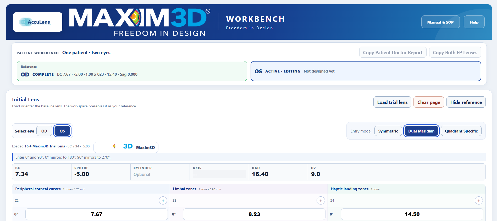
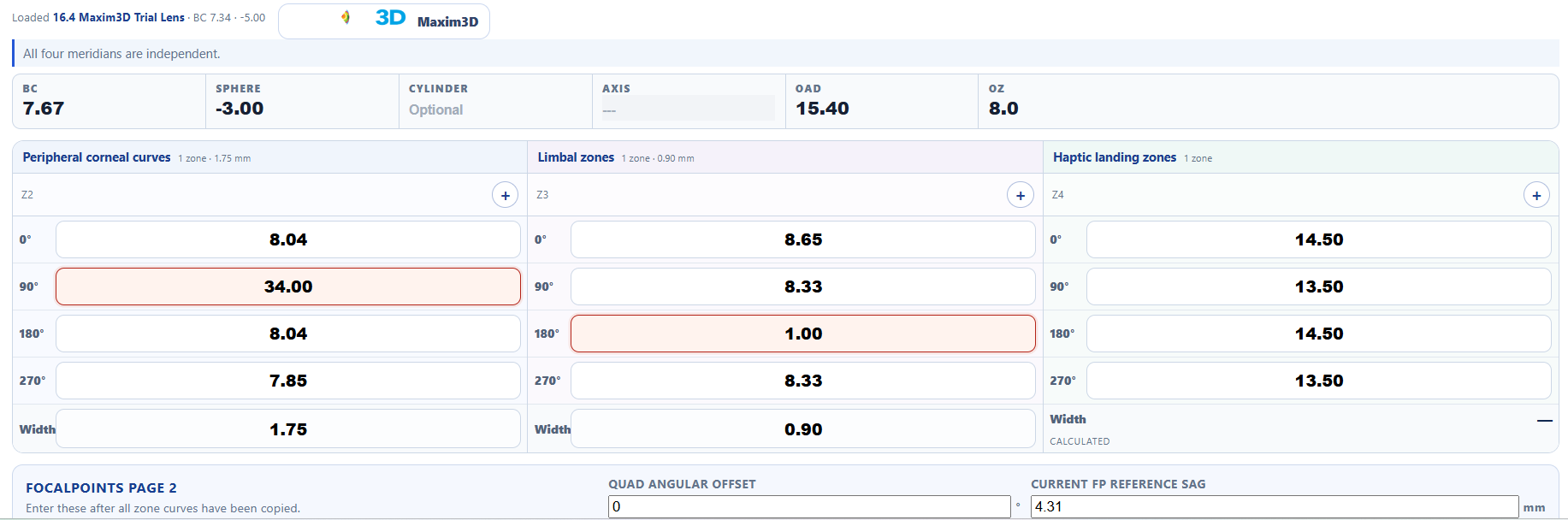
Existing lens entry beside the angle-offset orientation diagram
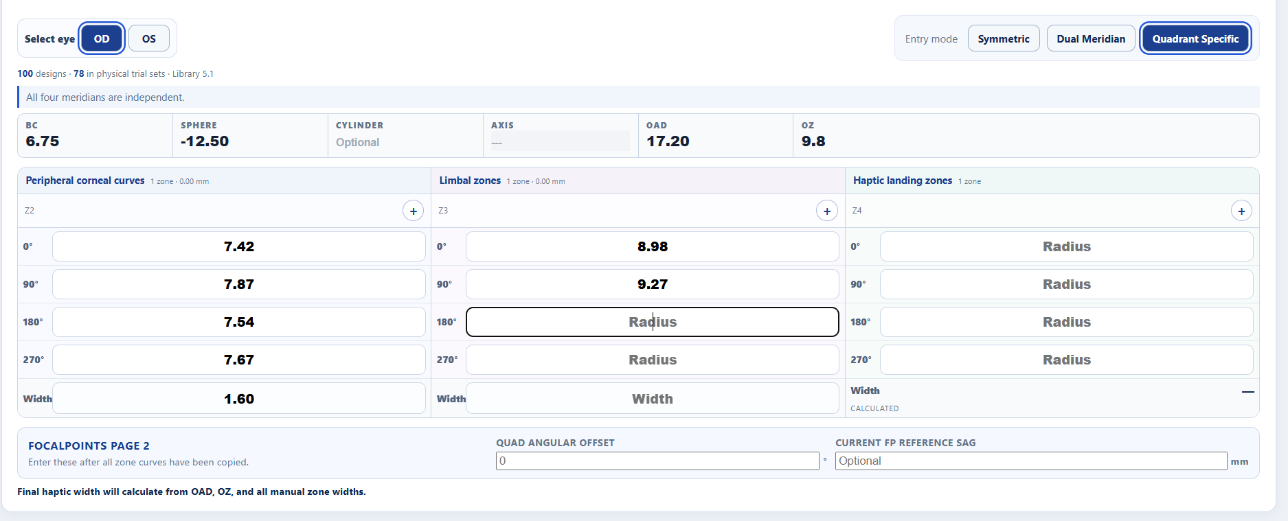
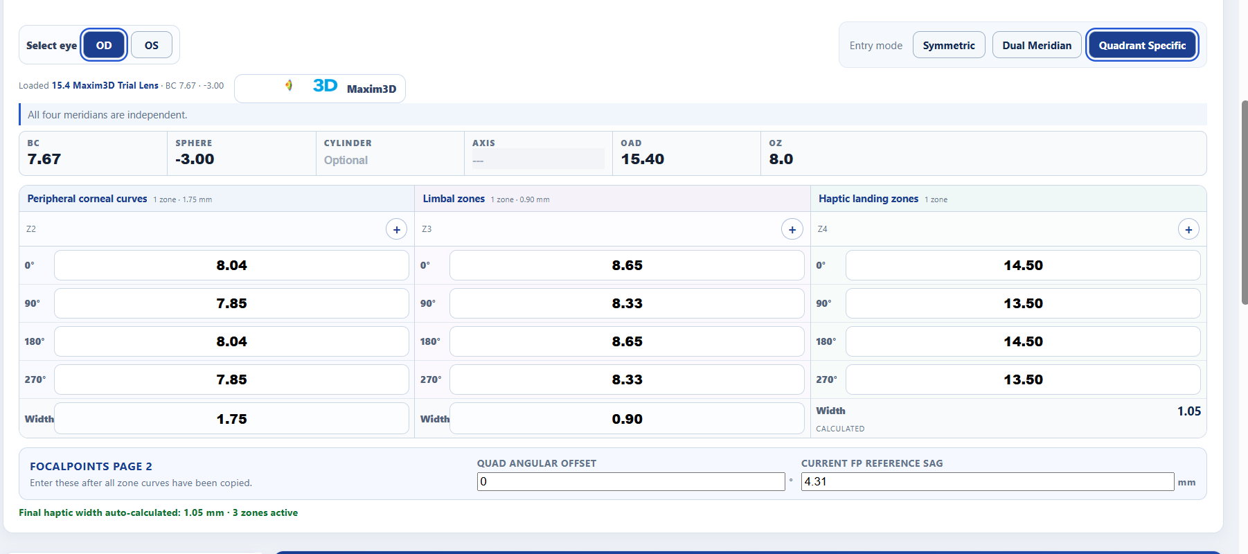
Existing-lens entry mirrors FocalPoints order. The orientation card shows where each input meridian lands on the eye.
Load Existing LensEnter the current FocalPoints lens or load a trial lens.
Lens OrientationShows the signed quad angular offset and input-to-eye mapping.
Optical AdjustmentCombines current Rx, over-refraction, vertexing, and observed rotation.
Modification WorkspaceDisplays current radius, requested sag change, new radius, and resulting total sag together.
04

Load an existing lens

Select the design mode first, then transcribe the lens in the same sequence used in FocalPoints.

1

Select entry mode: Symmetric, Dual Meridian, or Quadrant Specific.

2

Enter BC, sphere, optional cylinder and axis, diameter, and OZ.

3

Enter Z2 at 0°, 90°, 180°, and 270°, followed by Z2 width.

4

Enter Z3 at 0°, 90°, 180°, and 270°, followed by Z3 width.

5

Enter Z4 at 0°, 90°, 180°, and 270°. Z4 width is calculated automatically from OAD, OZ, Z2 width, and Z3 width.

6

On the FP Page 2 row, enter the signed quad angular offset and optional current FP reference sag.

BC → Power → Diameter → OZ → Z2 ×4 → Z2 width → Z3 ×4 → Z3 width → Z4 ×4 → Offset → FP Sag

Design modes

ModeEditable meridiansMirroring behavior
SymmetricMirrors to 90°, 180°, and 270°
Dual Meridian0° and 90°0° mirrors to 180°; 90° mirrors to 270°
Quadrant SpecificAll fourEach meridian remains independent
05

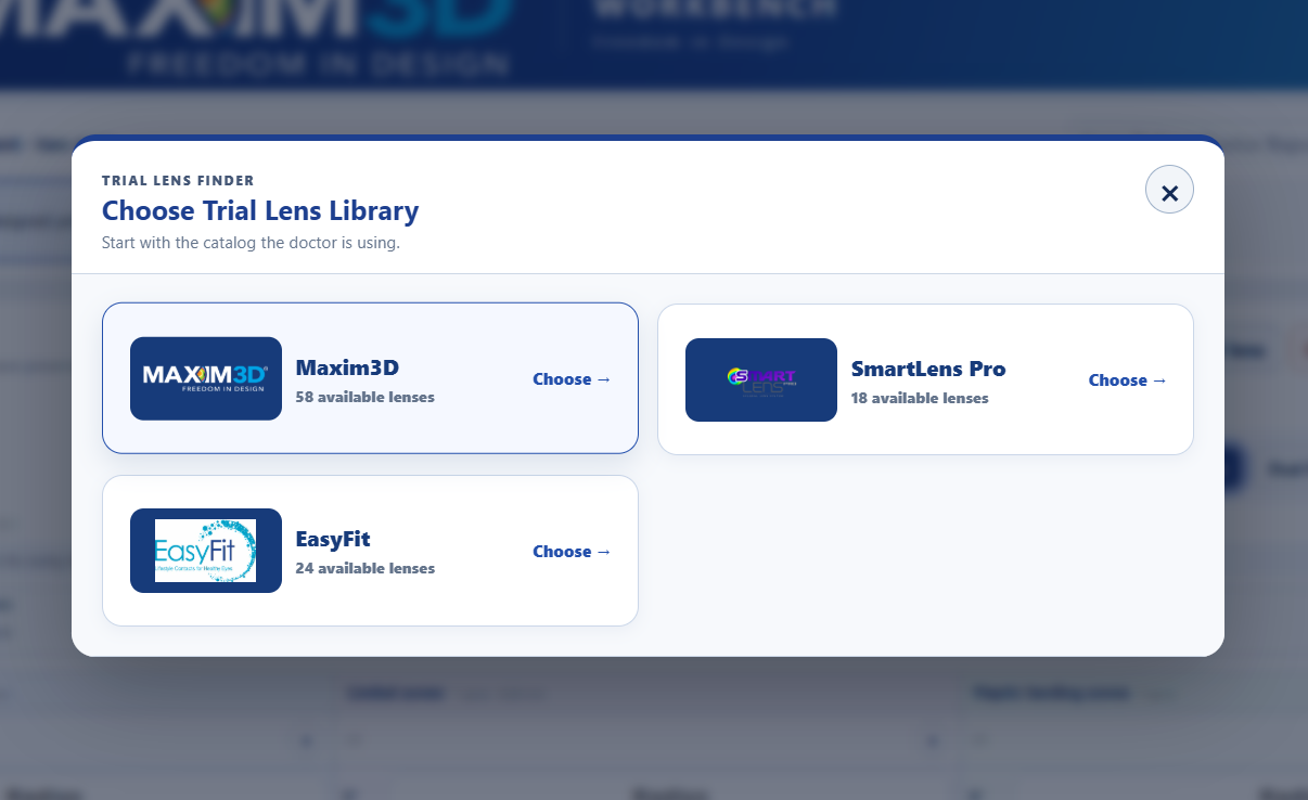
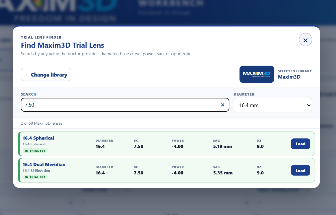
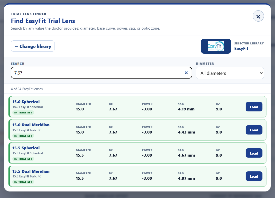
Load a trial lens

Select Load trial lens to open the searchable library. The library contains 15.4, 15.9, and 16.4 mm families, each available as Spherical or Dual Elevation.

In trial set

Green-highlighted lenses are physically included in the standard trial set.

Additional design

Gray lenses are valid library designs but are not included in the physical set.

Each card displays BC, power, OAD/OZ, and reference sag. Selecting a lens fills its mode, curves, widths, power, and reference sag automatically.

Library note: High Toric/TPC lenses are intentionally excluded. Toric and bi-elevation duplicates are consolidated under Dual Elevation.
06

Over-refraction and rotation

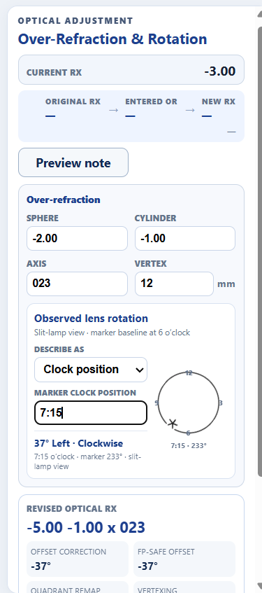
Use the Optical Adjustment panel before geometric modification when the lens requires an Rx change, rotation compensation, or both.

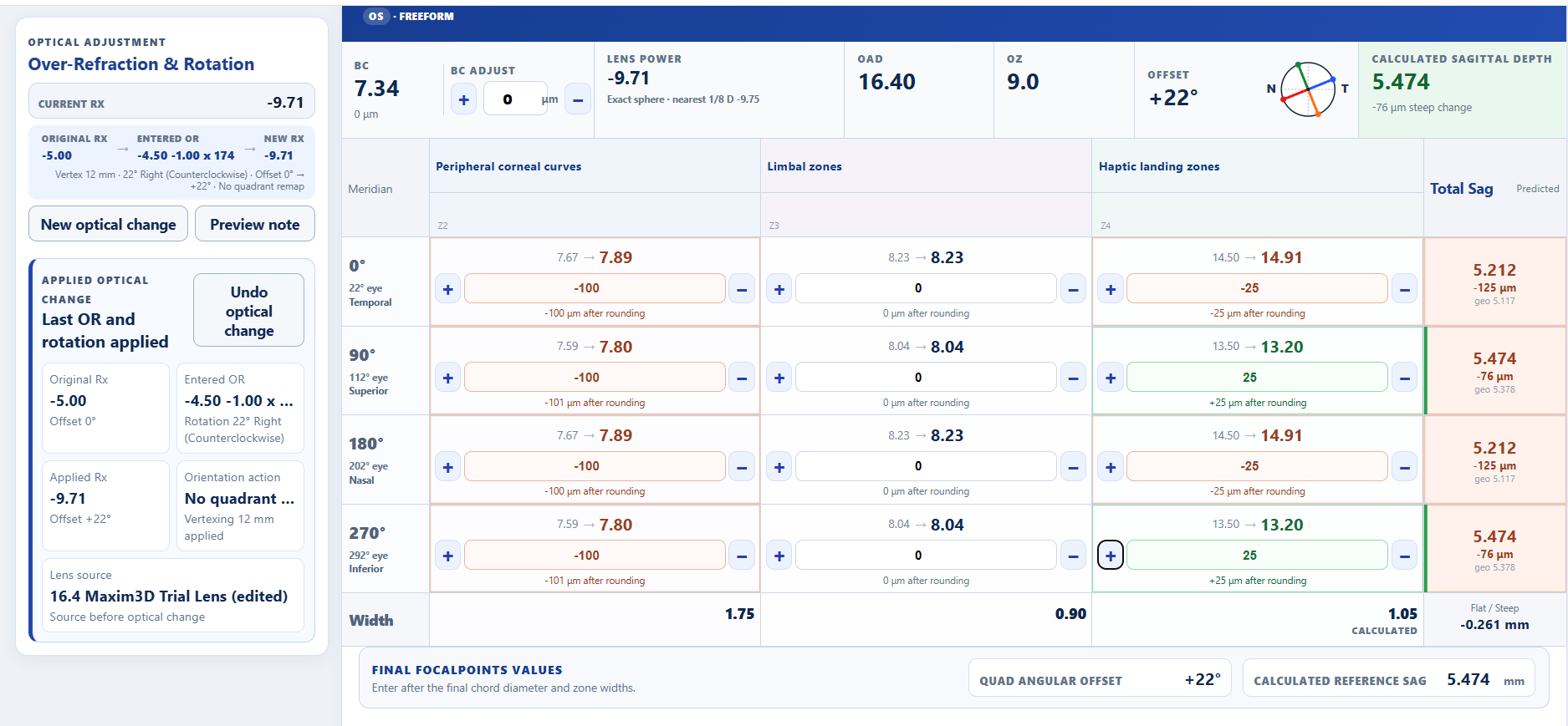
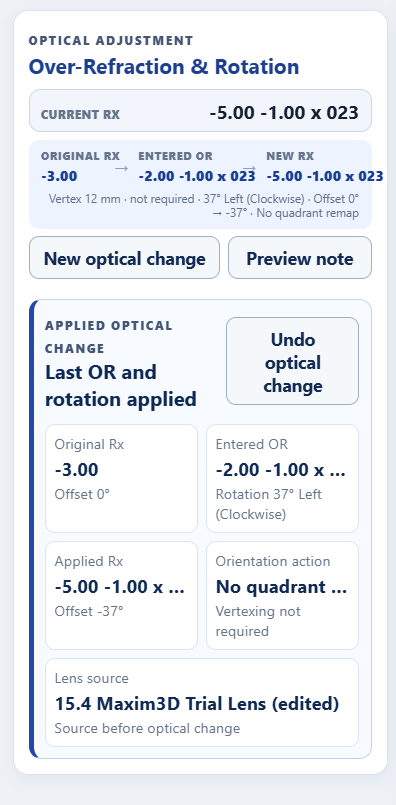
Over-refraction and rotation panel with applied change history
The optical panel shows either the active input calculation or the applied-change history.

Procedure

1

Enter the over-refraction sphere, cylinder, and axis. Positive and negative values are accepted.

2

Confirm vertex distance. The default is 12 mm. The engine vertices principal meridians when required.

3

Enter observed lens rotation in degrees and select Clockwise or Counterclockwise.

4

Review revised optical Rx, offset correction, FP-safe offset, quadrant remap, and vertexing note.

5

Select Apply optical changes. The tool updates Rx and orientation and preserves a visible history record.

Rotation and FP offset

FocalPoints accepts offsets from −45° through +45°. When a correction crosses that range, the Modifier rotates the quadrant basis by 90°, remaps Z2–Z4 and existing sag adjustments, and returns an equivalent FP-safe offset.

After applying: confirm Original Rx, Entered OR, Applied Rx, original and new offset, rotation direction, remap action, and vertexing status.
07

Sag-based modification

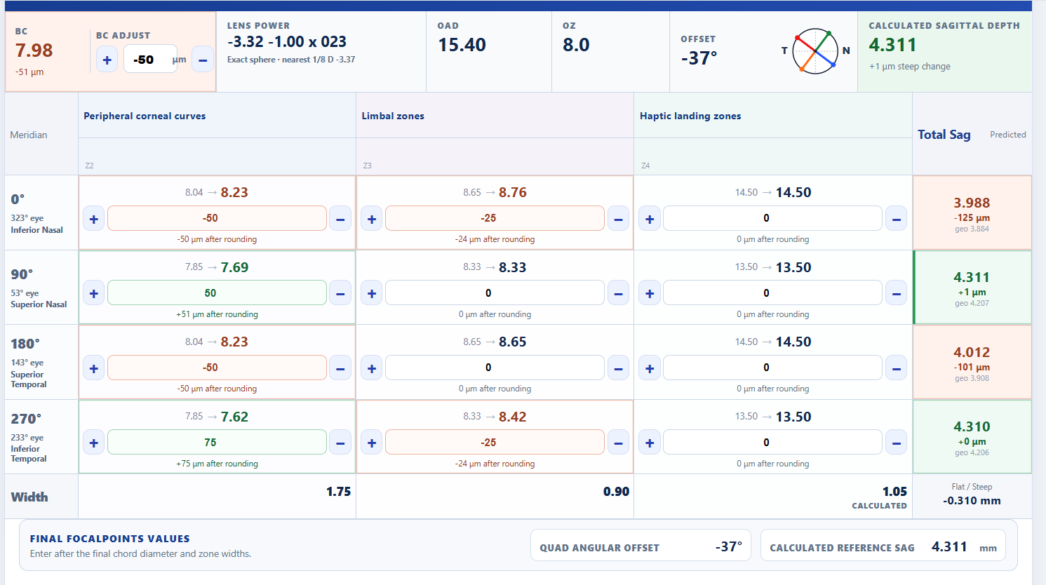
Enter the desired sag contribution change in microns. The Modifier calculates a revised radius and then rechecks the actual sag change produced after rounding to FP's 0.01 mm radius precision.

Modification workspace with zone adjustments and total sag per quadrant
Each zone cell contains the current radius, sag adjustment, revised radius, and achieved change after rounding.
Positive (+)Increases the sag contributed by that zone.
Negative (−)Decreases the sag contributed by that zone.

How zone adjustments accumulate

A zone adjustment changes that zone's local rise and therefore changes every cumulative landmark beyond it. For example:

Z2 −150 µm+Z3 +50 µm=Net edge sag −100 µm
  • BC: global optic-zone sag change; power is compensated accordingly.
  • Z2: secondary-zone contribution.
  • Z3: intermediate-zone contribution.
  • Z4: haptic-zone contribution.

The Total Sag column displays the predicted FP sag for each quadrant and identifies the steepest resulting meridian.

08

Review and copy results

Before entering the revised design into FocalPoints, verify the following:

Select Copy new lens to copy the revised specifications in FP-friendly order. Enter the values into a duplicated or saved FocalPoints order, then compare the FP reference sag with the prediction.

Expected variation: FP may differ slightly because of internal blending and reference-surface conventions. The Modifier is optimized to preserve the requested change rather than duplicate every hidden absolute-sag convention.
09

Undo, reset, and clear

ControlEffect
Undo optical changeRestores the preceding Rx, offset, curves, and any sag adjustments rotated during remapping.
New optical changeOpens a blank OR/rotation input while preserving the lens currently applied.
Reset adjustmentsReturns BC, Z2, Z3, and Z4 sag adjustments to zero without removing the loaded lens.
Collapse entry / Edit lensHides or restores the lens-entry panel to reduce scrolling.
Clear pageAfter confirmation, removes the lens, optical history, and all adjustments.
10

Clinical examples

Geometry

Reduce Z2 sag while adding some depth back in Z3

Goal: Z2 −150 µm; Z3 +50 µm.

Expected net: approximately −100 µm at the lens edge, subject to FP radius rounding.

Rotation

Compensate a rotated quadrant-specific lens

Enter the observed degrees and direction. If the correction exceeds FP's ±45° range, review the automatic 90° quadrant remap before applying.

Optics

Apply an oblique over-refraction

Enter sphere, cylinder, and axis. The tool transposes as needed, vertices principal meridians, combines Rx in power-vector space, and returns minus-cylinder notation.

Trial lens

Convert a trial lens into a custom design

Load the trial lens, apply OR/rotation if present, then make quadrant-specific sag changes while retaining the original set geometry as the baseline.

11

Troubleshooting

The workspace does not calculate.

Confirm that BC, diameter, OZ, all required curves, and Z2/Z3 widths are complete. Check that the calculated Z4 width is positive.

The predicted FP sag does not match exactly.

Confirm the current FP reference sag, OZ, diameter, widths, and offset. Small absolute differences are expected; compare the requested sag change and the achieved change after radius rounding.

The offset correction crosses ±45°.

The tool should display a 90° quadrant remap and an equivalent legal FP offset. Review the applied-change history and the new meridian order before copying.

The optical result looks wrong by roughly twice the rotation.

Recheck Clockwise versus Counterclockwise. Confirm that the direction describes the observed lens movement using the convention displayed in the tool.

A trial lens is missing.

Confirm the diameter and family filters. High Toric/TPC designs are intentionally excluded. Green items are physical set lenses; gray items are additional supported designs.

I applied an incorrect OR.

Select Undo optical change. This restores the previous power, offset, quadrant curves, and rotated sag adjustments.

12

Glossary

BC
Back central radius of the optic zone.
OAD / Diameter
Overall lens diameter, measured edge to edge.
OZ
Back optic zone diameter.
Z2
Secondary peripheral zone immediately outside the optic zone.
Z3
Intermediate peripheral zone.
Z4
Haptic or landing zone.
Sag adjustment
Requested change in a zone's sag contribution, entered in microns.
Quad angular offset
Orientation of the four meridian inputs on the eye; FP accepts −45° to +45°.
OR
Over-refraction performed over the existing lens.
Dual Elevation
Two-meridian design with 0°/180° paired and 90°/270° paired.
13

Revision history

SOP versionSoftwareDateDescription
1.0v4.2July 2026Initial interactive manual and SOP covering lens entry, trial library, optical changes, rotation remapping, and sag modification.
Prepared by____________________________
Reviewed by____________________________
Approved by____________________________
Effective date____________________________